
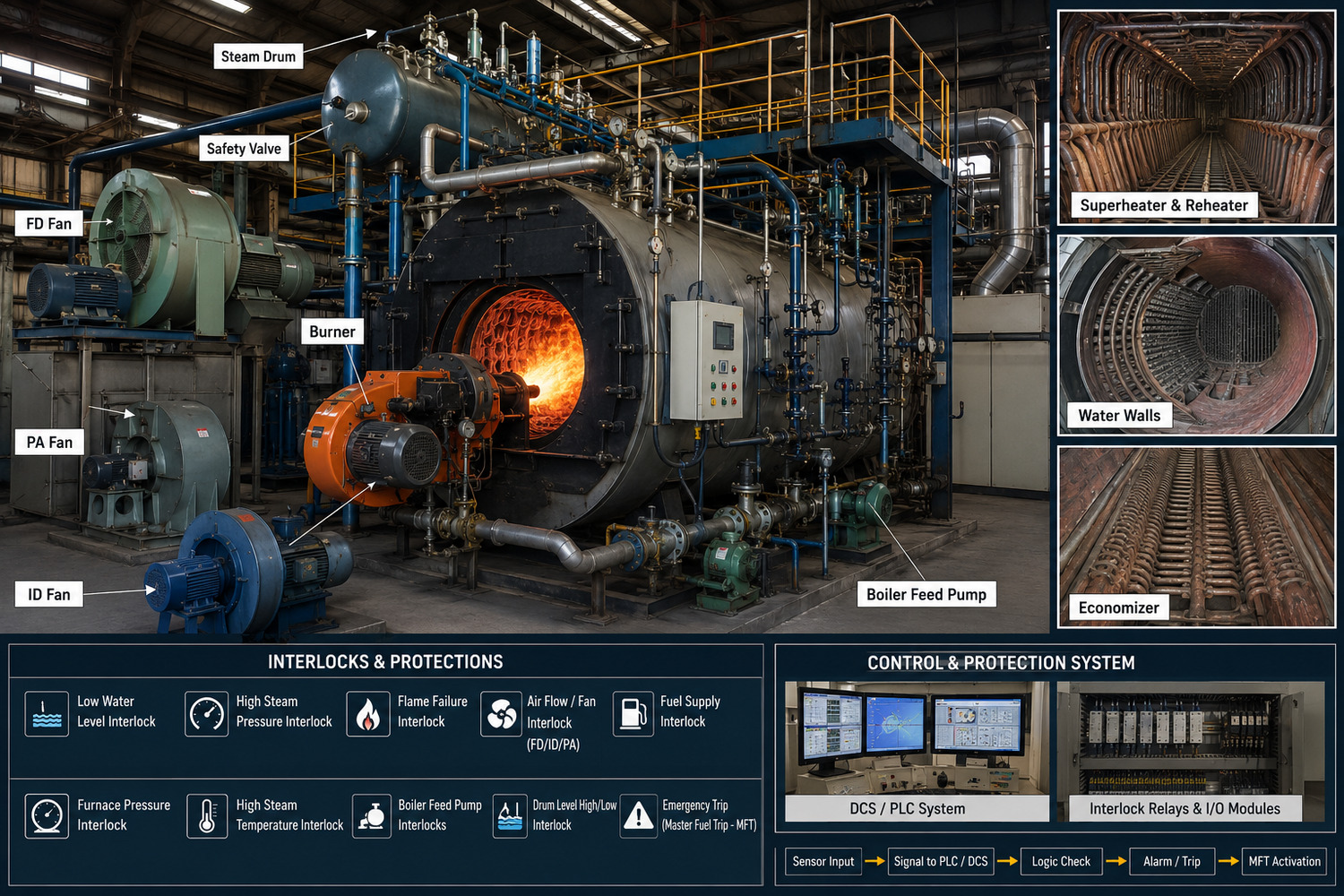
In a thermal power plant, boilers play a vital role in operation. Due to their exposure to high pressure and temperature, maintaining safety becomes extremely important. Safety interlocks are installed to minimize risks and prevent damage to equipment.
Types of Safety Interlocks in Boilers
Furnace Purge Interlock
Before boiler startup, the furnace must be cleared of any unburnt fuel gases.
-
Ensures adequate airflow for a specified duration.
-
Eliminates residual combustible gases.
-
Reduces the risk of explosion during ignition.
-
Mandatory step before burner light-up.
Low Water Level Interlock
Maintaining the correct water level is essential for safe boiler operation.
-
Trips the boiler when water level drops below the safe limit
-
Prevents overheating of boiler tubes
-
Avoids serious equipment damage
-
Considered one of the most critical protections
High Steam Pressure Interlock
Boilers are designed to operate within defined pressure limits.
-
Cuts off fuel supply if pressure exceeds the set value
-
Works in coordination with safety valves
-
Prevents over-pressurization and explosion risks
Flame Failure Interlock
Stable flame is necessary for continuous combustion.
-
Detects flame loss inside the furnace
-
Instantly shuts off fuel supply
-
Prevents accumulation of unburnt fuel
-
Reduces chances of furnace explosion
Forced Draft (FD) Fan Interlock
Proper air supply is required for efficient combustion.
-
Ensures FD fan operation before fuel admission
-
Trips the boiler if airflow is inadequate
-
Maintains proper air-fuel ratio
Induced Draft (ID) Fan Interlock
Maintains negative pressure inside the furnace.
-
Ensures proper evacuation of flue gases
-
Prevents positive pressure buildup
-
Protects against gas leakage into surroundings
Fuel Supply Interlock
Controls safe and regulated fuel feeding.
-
Allows fuel flow only when all safety conditions are satisfied
-
Stops fuel supply during abnormal situations
-
Integrated with multiple safety systems
Drum Level High/Low Interlock
Regulates water level in the steam drum.
-
Trips boiler during extremely high or low levels
-
Prevents carryover of water with steam
-
Avoids exposure of boiler tubes
-
Ensures stable boiler operation
Air Flow Interlock
Adequate airflow is essential for combustion efficiency.
-
Monitors air pressure and flow rate
-
Trips the system if airflow is insufficient
-
Ensures safe and complete combustion
Emergency Trip Interlock (Master Fuel Trip – MFT)
This is the ultimate safety protection system in a boiler.
-
Instantly shuts off all fuel supply
-
Activated during major faults or unsafe conditions
-
Prevents severe damage and potential accidents
AFBC Boiler Interlocks: Key Safety Features and Working Principles
AFBC (Atmospheric Fluidized Bed Combustion) boilers are widely used in thermal power plants due to their fuel flexibility and efficient combustion. However, safe operation is critical because of high temperatures, pressure, and continuous fuel feeding.
To ensure safety, interlock systems are used to monitor and control boiler conditions automatically.
Furnace Purge Interlock: Crucial for clearing accumulated combustible gases before ignition, usually lasting a set time with fans at high capacity.
Bed Temperature Interlock: In AFBC, bed temperature (usually) must be monitored. High temperature causes clinker formation; low temperature leads to fuel instability.
Primary Air (PA) Fan Interlock: Essential for fluidization. Failure trips the coal feeders to prevent bed collapse.
Secondary Air (SA) Fan Interlock: Maintains proper air-fuel mixing and improves combustion efficiency.
Induced Draft (ID) Fan Interlock: Ensures negative pressure, protecting against leakage of hot, harmful gases.
Fuel Feeding Interlock: Ensures that coal is only fed when the bed is at the correct temperature (typically) and fluidized, preventing "puffing" or dangerous fuel accumulation.
Low/High Drum Level Interlock: Critical protection to prevent tube failure (dry firing).
High Steam Pressure Interlock: Acts as a secondary protection to prevent overpressure.
Flame/Combustion Stability Interlock: In FBC, this is often linked to monitoring bed temperature and PA flow, rather than just a traditional flame scanner.
Ash Handling Interlock: Prevents clogging of ash discharge systems, which can lead to bed defluidisation.
Master Fuel Trip (MFT): The main safety system that immediately cuts off all fuel when critical conditions (like low-low drum level, loss of all fans, or extreme furnace pressure) are met.
Working Principle of AFBC Interlocks
All interlocks are connected through a control system (DCS/PLC)
Sensors continuously monitor parameters like:
Temperature
Pressure
Air flow
Water level
If any parameter goes beyond safe limits:
Alarm is generated
Automatic trip (MFT) is activated if required
Boiler Feed Pump Interlocks: Protection Logic and Operational Importance
Boiler Feed Pump interlocks are automatic safety and protection systems that ensure the pump operates only under safe conditions.
-
Low Suction Pressure Interlock
-
Low Deaerator Level Interlock
-
Minimum Flow (Recirculation) Interlock
-
Motor Overload Interlock
-
Bearing Temperature High Interlock
-
Vibration High Interlock
-
Seal Failure / Leakage Interlock
-
Discharge Pressure High/Low Interlock
-
Auto Start Interlock (Standby Pump)
-
Power Supply Failure Interlock
If any unsafe condition occurs, these interlocks will
-
Prevent the pump from starting, or
-
Shut down the running pump to avoid damage
Protection Logic
Sensors continuously monitor :-
Pressure
Flow
Temperature
Vibration
Water level
These signals are sent to DCS/PLC system
Logic conditions are applied:
If parameter is within limit → Pump runs normally
If parameter crosses limit → Alarm
If parameter reaches critical level → Pump trip
Operational Importance of BFP Interlocks
-
Prevents pump damage and costly repairs
-
Ensures continuous water supply to boiler
-
Avoids boiler trip due to low drum level
-
Improves equipment life and reliability
-
Enhances overall plant safety
Reheater Protection in Boilers: Preventing Overheating and Tube Failure
The reheater operates at extremely high temperatures and, unlike boiler tubes, it does not have direct water cooling. This makes it more susceptible to overheating.
To avoid damage, proper reheater protection systems and safety interlocks are essential.
Steam Flow Low Protection – Prevents overheating when steam flow is insufficient.
Reheater Tube Metal Temperature High Protection – Protects tubes from excessive metal temperature.
Flue Gas Temperature High Protection – Trips on high gas temperature around reheater.
Reheater Outlet Steam Temperature High Protection – Controls and limits outlet steam temperature.
Attemperator (Spray) Failure Protection – Acts when the spray system fails to control temperature.
Furnace Safeguard / MFT Protection – Cuts off fuel during major faults.
Bypass System Protection – Ensures steam flow during startup or low load.
Draft (FD/ID Fan) Failure Protection – Prevents improper gas flow and heat buildup.
Gas Flow Imbalance Protection – Avoids uneven heating across reheater tubes.
Reheater Overheating Protection – Overall protection against excessive heat exposure.
Common Boiler Protection Systems Used in Thermal Power Plants
-
Low Drum Water Level Protection – Trips boiler to prevent tube overheating.
-
High Drum Water Level Protection – Prevents water carryover to turbine.
-
High Steam Pressure Protection – Protects boiler from overpressure conditions.
-
Furnace Purge Interlock – Clears unburnt gases before ignition.
-
Flame Failure Protection – Cuts off fuel when flame is lost.
-
Master Fuel Trip (MFT) – Emergency shutdown of boiler fuel supply.
-
FD Fan Interlock – Ensures proper air supply for combustion.
-
ID Fan Interlock – Maintains furnace draft and gas removal.
-
PA Fan Interlock – Provides air for fuel combustion (especially in coal boilers).
-
Air Flow Protection – Ensures adequate air for safe combustion.
-
Fuel Supply Interlock – Allows fuel only under safe conditions.
-
Furnace Pressure High/Low Protection – Prevents furnace explosion or implosion.
-
Superheater Temperature High Protection – Protects tubes from overheating.
-
Reheater Protection – Prevents overheating due to low steam flow.
-
Boiler Tube Leak Detection – Detects leakage and prevents major failure.
-
Feed Pump Interlocks – Ensures safe operation of boiler feed pump.
Final Insight
-
All protections are linked with MFT for immediate action
-
Regular testing and maintenance is very important
-
Bypassing protection is unsafe and strictly prohibited
How Interlock Systems Prevent Boiler Trips and Failures
This is where interlock systems play a vital role, acting as a safety barrier to prevent unsafe operation and minimize the risk of failure.
Ensure safe startup by allowing operation only when all conditions are normal.
Continuously monitor key parameters like drum level, pressure, and temperature.
Give early alarms to help operators take action in time.
Perform automatic corrections (like starting standby equipment).
Trip the boiler during critical conditions to prevent damage.
Activate Master Fuel Trip (MFT) to stop fuel supply instantly.
Best Practices for Maintaining Boiler Safety Interlocks
-
Regular Testing – Periodically test all interlocks to ensure proper operation.
-
Calibration of Sensors – Keep pressure, temperature, and level sensors accurate.
-
No Bypass Policy – Never bypass interlocks during operation.
-
Routine Inspection – Check wiring, instruments, and control logic regularly.
-
Proper Documentation – Maintain updated interlock logic and records.
-
Training of Operators – Ensure operators understand interlock functions.
-
Preventive Maintenance – Follow scheduled maintenance for all instruments.
-
Alarm Verification – Ensure alarms are working before trip conditions.
-
DCS/PLC Health Check – Keep control system reliable and updated.
-
Spare Management – Maintain critical spares for quick replacement.
Essential Interlock Conditions in AFBC Boilers
-
Furnace Purge Completed – Ensures removal of unburnt gases before light-up.
-
PA Fan Running – Required for proper bed fluidization.
-
ID Fan Running – Maintains negative furnace pressure.
-
Adequate Air Flow Available – Ensures safe combustion.
-
Bed Temperature in Safe Range – Prevents improper combustion or damage.
-
Fuel Feeding Permissive – Fuel allowed only when all conditions are safe.
-
Drum Water Level Normal – Prevents dry heating or carryover.
-
Steam Pressure Within Limit – Ensures safe boiler operation.
-
No Furnace Pressure Abnormality – Avoids explosion or implosion.
-
Ash Handling System Healthy – Prevents bed choking and buildup.
-
No Active Trip (MFT Reset) – Boiler start allowed only after clearing trips.
Start-up and Shutdown Interlocks in Boiler Systems
Start-up Interlocks
-
Furnace Purge Completed – Clears unburnt gases to prevent explosion
-
FD/ID Fans Running – Ensures proper air flow and draft
-
Adequate Drum Water Level – Prevents dry heating of tubes
-
Fuel System Ready – Fuel supply available under safe conditions
-
Air Flow Available – Required for safe combustion
-
No Active Trip (MFT Reset) – All previous trips cleared
-
Ignition System Healthy – Ensures safe burner light-up
-
Purpose: Allow boilers start only when all safety conditions are met.
Shutdown Interlocks (During Boiler Trip/Stop)
-
Master Fuel Trip (MFT) – Immediately cuts off fuel supply
-
Post Purge Operation – Clears remaining combustible gases
-
FD/ID Fans Continue Running – Removes heat and flue gases safely
-
Feed Water Control Active – Maintains safe drum level during shutdown
-
Temperature Control (Cooling) – Prevents thermal stress on tubes
-
Turbine/Load Coordination – Ensures safe load reduction
Ensure safe and controlled shutdown without damage
Critical Parameters Monitored in Boiler Protection Systems
Key Parameters
-
Drum Water Level – Prevents dry heating and water carryover.
-
Steam Pressure – Avoids overpressure and explosion risk.
-
Steam Temperature – Protects superheater/reheater tubes.
-
Furnace Pressure – Prevents explosion or implosion.
-
Flue Gas Temperature – Indicates overheating or fouling.
-
Air Flow – Ensures proper combustion.
-
Fuel Flow – Maintains correct air-fuel ratio.
-
Flame Status – Detects flame failure instantly.
-
Feed Water Flow – Ensures continuous water supply.
-
Bed Temperature (AFBC) – Maintains proper combustion condition.
-
Draft (FD/ID/PA Fans) – Ensures safe gas flow and furnace draft.
-
Tube Metal Temperature – Detects overheating of boiler tubes
Boiler Feed Pump Trip Conditions and Safety Checks
BFP Trip Conditions
-
Low Suction Pressure – Prevents cavitation and pump damage
-
Low Deaerator Level – Avoids dry running of pump
-
Motor Overload / Electrical Fault – Protects motor from damage
-
Bearing Temperature High – Prevents bearing failure
-
Vibration High – Indicates mechanical issues
-
Seal Failure / Leakage High – Protects pump from seal damage
-
Discharge Pressure High/Low – Prevents abnormal operation
-
Minimum Flow Not Maintained – Avoids overheating of pump
-
Power Supply Failure – Trips pump during voltage/phase issues
Safety Checks Before Start
-
Suction Valve Open – Ensures water availability
-
Discharge Valve Position Correct – Safe startup condition
-
Minimum Flow Line Open – Protects pump during low load
-
Adequate Deaerator Level – Sufficient water source
-
Lubrication System Healthy – Bearings properly lubricated
-
No Abnormal Vibration/Noise – Mechanical health check
-
Electrical System Healthy – No fault in motor or panel
Reheater Temperature Control and Protection Methods
Temperature Control Methods
-
Spray Attemperator Control – Uses water spray to control steam temperature
-
Flue Gas Flow Control – Adjusts gas flow using dampers to regulate heat
-
Burner Tilt / Firing Control – Controls heat input to reheater zone
-
Gas Bypass System – Diverts hot gases to maintain temperature
-
Load Control – Adjusts boiler load to stabilize temperature
Protection Methods
-
Steam Flow Low Protection – Prevents overheating without steam flow
-
Tube Metal Temperature High Protection – Protects reheater tubes
-
Flue Gas Temperature High Protection – Avoids excessive heating
-
Reheater Outlet Temperature High Protection – Limits steam temperature
-
Attemperator Failure Protection – Acts when spray system fails
-
Furnace Safeguard (MFT) – Cuts fuel during critical conditions
Common Causes of Interlock Activation in Thermal Plants
Interlock systems in thermal power plants are designed to protect equipment and ensure safe operation. When any critical parameter goes beyond safe limits, interlocks activate alarms or trips.
Understanding the common causes helps in reducing unnecessary trips and improving reliability.
Common Causes
-
Low Drum Water Level – Insufficient feed water supply
-
High Drum Water Level – Overfeeding or control failure
-
Flame Failure – Loss of ignition or unstable combustion
-
Air Flow Low / Fan Trip (FD/ID/PA) – Loss of proper draft or air supply
-
Fuel Supply Issues – Coal feeder trip or fuel interruption
-
High Furnace Pressure – Draft imbalance or gas buildup
-
Low Steam Flow – Load drop or blockage in system
-
High Steam Pressure/Temperature – Overfiring or control malfunction
-
Feed Pump Trip – Loss of water supply to boiler
-
High Vibration / Temperature (Equipment) – Mechanical faults in pumps/fans
-
Electrical Faults – Power failure, relay or breaker trip
-
Instrumentation Failure – Wrong or no signal from sensors
Troubleshooting Boiler Interlock Failures
What Is an Interlock Failure?
-
False Trip – Interlock activates without actual fault
-
Failure to Trip – Interlock does not activate during unsafe condition
-
Start Block Issue – Boiler does not start even when conditions seem normal
Common Causes of Interlock Failures
-
Faulty sensors (pressure, temperature, level transmitters)
-
Wiring or signal issues
-
DCS/PLC logic errors
-
Calibration problems
-
Power supply fluctuations
-
Human error or incorrect settings
Troubleshooting Approach
-
Identify the Interlock
-
Check DCS alarm/trip and note the exact parameter
-
Verify Field Condition
-
Cross-check DCS readings with actual field condition
-
Check Sensors
-
Inspect transmitters for calibration, damage, or signal issues
-
Inspect Wiring
-
Check all cables and connections for any loose fittings or faults
-
Check Logic (DCS/PLC)
-
Verify interlock logic and setpoints
-
Check Equipment
-
Inspect related pumps, fans, valves (e.g., BFP condition)
-
Review Trends
-
Analyze alarm history to find root cause
-
Fix the Issue
-
Repair, recalibrate, or correct settings
-
Reset & Test
-
Reset interlock and test before restart
Conclusion
Boiler interlocks are essential for safe, reliable, and efficient operation of thermal power plants. They continuously monitor critical parameters and take immediate action to prevent accidents, equipment damage, and unexpected failures.
From startup to shutdown, interlocks ensure that the boiler operates only under safe conditions and automatically responds to any abnormal situation.
A strong interlock system, combined with proper maintenance, regular testing, and skilled operation, is the key to minimizing trips and ensuring long-term plant reliability.