
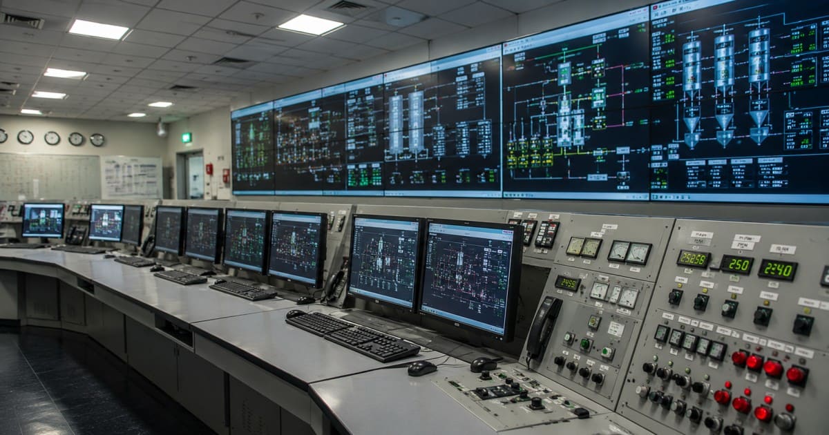
A Distributed Control System (DCS) is an advanced automation system used in power plants to monitor, control, and optimize all major plant processes from a centralized control room, ensuring safe, reliable, and efficient operation.
Key Components of a DCS in Power Plants
A Distributed Control System (DCS) consists of several interconnected components that work together to monitor, control, and protect the entire power plant.
Field Instruments (Sensors & Transmitters)
These are installed in the plant to measure process parameters and send real-time data to the DCS.
Examples
1. Pressure Transmitters (PT)
2. Temperature Sensors (RTD/Thermocouple)
3. Flow Transmitters (FT)
4. Level Transmitters (LT)
Function
Measure process values
Send signals (typically 4–20 mA or digital) to the DCS
Final Control Elements
These devices receive commands from the DCS and control the process.
Examples
1. Control Valves
2. Motor Operated Valves (MOV)
3. Dampers
4. Variable Frequency Drives (VFDs)
Function
-
Regulate flow, pressure, level, and temperature
-
Execute automatic control actions
Input/Output (I/O) Modules
I/O modules act as the interface between field devices and DCS controllers.
Types
1. AI (Analog Input): Receives analog signals from sensors
2. AO (Analog Output): Sends analog commands to control devices
3. DI (Digital Input): Receives ON/OFF status signals
4. DO (Digital Output): Sends ON/OFF commands
DCS Controllers
Controllers are the brain of the DCS. They process inputs, execute control logic, and send output commands.
Functions
1. PID control
2. Interlock logic
3. Sequence control
4. Alarm processing
5. Automatic equipment operation
Communication Network
A high-speed, redundant industrial network connects all DCS components.
Function
1. Transfers data between controllers, operator stations, and servers
2. Ensures reliable communication even if one network path fails
Operator Workstation (HMI)
The Human Machine Interface (HMI) allows operators to monitor and control the plant.
Functions
1. Process graphics
2. Equipment status
3. Alarm monitoring
4. Trend analysis
5. Start/Stop equipment
6. Setpoint adjustment
Engineering Workstation
Used by engineers to configure and maintain the DCS.
Functions
1. Logic programming
2. System configuration
3. Database management
4. Software updates
5. Diagnostics and troubleshooting
Historian Server
The historian stores process data continuously for future analysis.
Functions
1. Data logging
2. Trend analysis
3. Event recording
4. Performance reports
5. Power plant maintenance planning
Alarm & Event Management System
This system alerts operators whenever abnormal conditions occur.
Functions
1. High/Low process alarms
2. Equipment trip notifications
3. Fault diagnosis
4. Event recording with timestamps
Redundancy System
Redundancy ensures continuous operation even if a component fails.
Examples
1. Redundant Controllers
2. Redundant Power Supplies
3. Redundant Communication Networks
4. Redundant Servers
Benefit
1. High availability
2. Improved reliability
3. Minimal plant downtime
How does a DCS Control System Work?
Process Measurement
The DCS starts by collecting real-time data from field instruments installed throughout the power plant.
Common measurements include:
Temperature
Pressure
Flow
Level
Speed
Vibration
For example, a pressure transmitter measures the boiler steam pressure and sends the signal to the DCS.
Signal Transmission
The signals from sensors are transmitted to the Input/Output (I/O) modules.
The I/O modules
1. Receive analog and digital signals.
2. Convert analog signals into digital data.
3. Forward the information to the DCS controllers.
Data Processing in the Controller
The DCS controller compares the measured value with the desired setpoint.
Example
Boiler temperature setpoint = 540°C
Actual temperature = 532°C
The controller detects an 8°C difference and determines the required corrective action.
Decision and Control Action
Based on the controller's calculations, the DCS sends output commands to the final control elements.
Examples include
1. Opening or closing control valves
2. Starting or stopping motors
3. Adjusting damper positions
4. Changing pump or fan speed using VFDs
For example, if steam pressure drops, the DCS may open the fuel control valve to increase combustion and restore the pressure.
Process Adjustment
The control devices respond to the DCS commands, causing the process to change.
Examples
1. Fuel flow increases.
2. Feedwater flow adjusts.
3. Air damper position changes.
4. The turbine governor valve opens or closes.
These actions bring the process closer to the desired operating condition.
Setpoint
│
▼
DCS Controller
│
▼
Final Control Element
(Valve / Motor / Damper)
│
▼
Plant Process
(Turbine, Boiler Operations etc.)
│
▼
Field Instruments
│
└──────────► Feedback to Controller
Boiler Drum Level Control
1. The drum level transmitter detects a low water level.
2. The signal is sent to the DCS controller.
3. The controller compares the level with the setpoint.
4. The feedwater control valve is opened automatically.
5. More feedwater enters the boiler drum.
6. The drum level returns to the normal range.
7. The controller continuously adjusts the valve to maintain the correct level.
Advantages of a DCS Control System
1. Centralized Control: Monitor and control the entire plant from one control room.
2. High Reliability: Redundant controllers and networks reduce downtime.
3. Automatic Process Control: Maintains pressure, temperature, flow, and level automatically.
4. Improved Safety: Provides alarms, interlocks, and emergency shutdown functions.
5. Higher Efficiency: Optimizes fuel consumption and plant performance.
6. Real-Time Monitoring: Displays live process data and equipment status.
7. Faster Fault Detection: Quickly identifies faults for faster troubleshooting.
8. Data Logging: Stores process data for analysis and reporting.
9. Reduced Human Error: Automation minimizes manual mistakes.
10. Easy Expansion: New equipment and control loops can be added easily.
11. Lower Maintenance Costs: Supports predictive maintenance and reduces breakdowns.
12. Remote Monitoring: Enables engineers to monitor the plant remotely.
DCS Architecture in Power Plants
-
Field Instruments (Sensors & Transmitters)
-
I/O Modules (AI, AO, DI, DO)
-
DCS Controllers
-
Communication Network
-
Operator Workstations (HMI)
-
Engineering Workstation
-
Historian Server
-
Final Control Elements (Valves, Motors, Dampers)
Boiler Control & Combustion
1. Fuel and air flow control
2. Furnace pressure control
3. Drum level control
4. Steam temperature control
5. Combustion optimization
6. Burner management
7. Soot blower control
Turbine Management
1. Turbine speed control
2. Steam flow control
3. Governor valve control
4. Load control
5. Vibration monitoring
6. Bearing temperature monitoring
7. Turbine protection and trip
Emergency Shutdown System (ESD)
Detects emergency conditions
Generates emergency alarms
Trips critical equipment
Isolates unsafe systems
Protects personnel and equipment
Ensures safe plant shutdown
Environmental & Emissions Monitoring
1. Stack emission monitoring
2. SO2 monitoring
3. NOₓ monitoring
4. CO monitoring
5. Oxygen (O2) monitoring
6. Dust/Particulate monitoring
7. Environmental compliance reporting
Grid Synchronization & Load Distribution
1. Generator synchronization
2. Voltage matching
3. Frequency matching
4. Phase angle matching
5. Automatic load sharing
6. Grid load distribution
7. Generator protection
DCS Alarm System
1. High/Low process alarms
2. Equipment fault alarms
3. Priority-based alarm display
4. Audible and visual alerts
5. Alarm history recording
6. Operator acknowledgment
DCS Communication System
1. Communication between controllers
2. HMI and server communication
3. Data exchange with PLCs
4. Industrial Ethernet/Fiber Optic network
5. Redundant communication paths
6. High-speed real-time data transfer
DCS Interlock System
1. Prevents unsafe operations
2. Equipment permissive checks
3. Automatic equipment trips
4. Start/Stop interlocks
5. Sequence interlocks
6. Safety logic execution
DCS Information System
1. Real-time process monitoring
2. Historian data storage
3. Trend analysis
4. Event and alarm logging
5. Performance reporting
6. Maintenance data
7. Plant performance analysis
DCS Software
DCS (Distributed Control System) software is the brain of the control system. It allows operators and engineers to monitor, control, configure, and optimize the entire plant process from a central location.
Main Functions
1. Real-time process monitoring
2. Automatic process control
3. Alarm and event management
4. Historical data logging (Historian)
5. Trend analysis and reporting
6. Graphics (HMI) display
7. Controller programming and configuration
8. Communication with PLCs, RTUs, and field devices
9. User access and cybersecurity management
System Requirements for a DCS
A reliable DCS requires both hardware and software components to ensure continuous plant operation.
Hardware Requirements
Redundant DCS controllers
Operator and engineering workstations
Industrial servers
Industrial Ethernet network
I/O modules
UPS (Uninterruptible Power Supply)
Redundant power supplies
Network switches and firewalls
Software Requirements
Supported operating system
DCS engineering software
HMI software
Database/Historian software
Antivirus and cybersecurity software
Backup and recovery software
Network Requirements
High-speed Industrial Ethernet
Fiber optic communication (if required)
Redundant communication network
Secure remote access
Environmental Requirements
Temperature-controlled control room
Clean, dust-free environment
Stable power supply
Proper grounding and shielding
DCS System Upgrade
A DCS upgrade improves system reliability, performance, cybersecurity, and compatibility with modern technologies while minimizing plant downtime.
Why Upgrade?
1. Obsolete hardware replacement
2. Latest software features
3. Improved cybersecurity
4. Better HMI and graphics
5. Higher reliability
6. Faster processing
7. Easier maintenance
8. Support for new field devices
9. Reduced maintenance costs
Typical Upgrade Steps
1. Assess the existing DCS system.
2. Create backups of all configurations and databases.
3. Upgrade servers and workstations.
4. Upgrade controllers and I/O modules (if required).
5. Install the latest DCS software.
6. Test communication and control logic.
7. Perform Factory Acceptance Test (FAT) and Site Acceptance Test (SAT).
8. Train operators and maintenance engineers.
9. Commission and monitor the upgraded system.
Types of DCS Systems in Industrial Automation
Standalone DCS
A Standalone DCS is designed for small plants or individual process units. It operates independently without connecting to other DCS systems.
Features
Independent operation
Simple architecture
Easy installation and maintenance
Lower cost
Suitable for small-scale processes
Applications
Pharmaceutical laboratories
Food processing plants
Small manufacturing facilities
Water treatment plants
Distributed Control System Network (DCSN)
A DCS Network (DCSN) connects multiple DCS controllers and workstations through an industrial communication network. It enables centralized monitoring while maintaining distributed control.
Features
Multiple interconnected controllers
Centralized monitoring
High reliability and redundancy
Real-time data sharing
Easy plant expansion
Applications
Thermal power plants
Oil & gas refineries
Petrochemical plants
Large manufacturing industries
Hybrid DCS
A Hybrid DCS combines the capabilities of a DCS with other automation systems, such as PLCs and SCADA. Critical continuous processes are controlled by the DCS, while machine-level operations are handled by PLCs.
Features
Combines DCS, PLC, and SCADA
Flexible and scalable
Improved process efficiency
Better integration with existing systems
Cost-effective modernization
Applications
Chemical plants
Cement plants
Steel plants
Power plants with mixed automation systems
Cloud-Based DCS
A Cloud-Based DCS uses cloud technology to store, monitor, and analyze process data remotely. Operators can access plant information securely from anywhere.
Features
Remote monitoring and control
Cloud data storage
Real-time analytics
Predictive maintenance
Easy software updates
Scalable infrastructure
Applications
Wind farms
Solar power plants
Water utilities
Remote industrial facilities
Multi-site manufacturing companies
DCS System Training
DCS (Distributed Control System) training equips operators, technicians, and engineers with the knowledge and practical skills needed to safely operate, maintain, troubleshoot, and optimize industrial automation systems.
1. DCS Fundamentals
Introduction to DCS
Components of a DCS
DCS architecture
Communication networks
Difference between DCS, PLC, and SCADA
2. Operator Training
HMI navigation
Process monitoring
Alarm management
Trend analysis
Start-up and shutdown procedures
3. Engineering Training
Controller configuration
Control logic development
I/O configuration
Graphic display creation
Database management
4. Maintenance Training
Preventive maintenance
Controller and I/O diagnostics
Communication troubleshooting
System backup and restoration
Hardware replacement
5. Cybersecurity Training
User access management
Password and account security
Network security practices
Backup and disaster recovery
Software updates and patch management
6. Practical Exercises
Simulated plant operation
Alarm handling
Controller troubleshooting
Communication fault diagnosis
Backup and restore procedures
Emergency response drills
Challenges and Best Practices for DCS Implementation
Challenges
-
High initial investment
-
Complex system integration
-
Installation downtime
-
Cybersecurity risks
-
Skilled workforce requirement
-
Network and communication issues
-
Hardware/software compatibility
-
Regular maintenance and upgrades
Best Practices
-
Plan the project thoroughly
-
Choose the right DCS for the application
-
Use redundant controllers and networks
-
Implement strong cybersecurity measures
-
Provide regular operator training
-
Perform preventive maintenance
-
Keep software and firmware updated
-
Regularly back up system data
-
Test the system before commissioning
-
Continuously monitor and optimize performance