
Boilers convert fuel energy into steam essential for power generation and industrial processes. Among modern technologies, Fluidized Bed Combustion (FBC) boilers stand out for their high efficiency, fuel flexibility, and low emissions.
The two common types are Atmospheric Fluidized Bed Combustion (AFBC) and Circulating Fluidized Bed Combustion (CFBC).
What Is a Fluidized Bed Combustion Boiler?
A Fluidized Bed Combustion (FBC) boiler suspends solid fuel particles in a bed of inert material (typically silica sand) using an upward stream of air. This creates a fluid-like state that delivers turbulent mixing and superior combustion.
The process operates on the principle of fluidization, when air velocity from the bottom distribution system reaches a threshold, the bed material behaves like a boiling liquid, enabling efficient and uniform fuel burning.
Advantages of FBC Boilers over conventional grate-fired boilers:
-
Higher combustion efficiency
-
Better fuel flexibility (including low-grade fuels)
-
Lower NOx and SOx emissions
-
Uniform temperature distribution
-
Reduced maintenance requirements
-
Improved heat transfer rates
FBC systems are mainly classified into:
-
Atmospheric Fluidized Bed Combustion (AFBC)
-
Circulating Fluidized Bed Combustion (CFBC)
Atmospheric Fluidized Bed Combustion (AFBC) Boiler
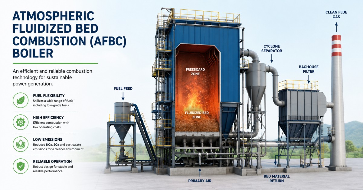
An AFBC boiler operates at atmospheric pressure with a relatively low fluidization velocity (1-3 m/s). Fuel burns in a stationary bubbling bed; bed particles remain largely within the combustion chamber.
Major Components of an AFBC Boiler:
-
Furnace with fluidized bed
-
Air distribution nozzles
-
Wind box
-
Bed coils
-
Fuel feeding system
-
Ash handling system
-
Boiler bank tubes
-
Economizer and air preheater
Common Applications:
-
Small and medium-sized power plants
-
Textile industries
-
Paper mills
-
Sugar industries
-
Food processing plants
-
Chemical industries
AFBC Boiler Working Principle
The fluidization process starts when primary air is supplied through air nozzles beneath the bed. As the velocity increases, the sand/ash bed becomes suspended.
Fuel (coal, lignite, biomass, pet coke) is fed into this turbulent zone, where combustion occurs in three stages: drying, release of volatile gases, and burning of fixed carbon. Continuous mixing ensures minimal unburnt carbon losses.
Combustion temperature stays within 800°C to 900°C, suppressing NOx formation. Heat is transferred by radiation, convection, and direct contact with submerged bed coils.
Process Flow Diagram:
Air Flow: FD Fan → Wind Box → Air Distribution Plate → Air Nozzles → Fluidized Bed → Furnace → Flue Gas
Fuel Flow: Fuel Hopper → Fuel Feeder → Furnace → Fluidized Bed Combustion Zone
Bed Material Flow: Bed Ash/Sand → Fluidized Bed → Continuous Mixing → Ash Removal System
Steam/Water Flow: Feed Water → Economizer → Drum → Water Wall Tubes → Bed Coils → Superheater → Steam Header → Turbine/Process
Flue Gas Flow: Furnace → Superheater → Economizer → Air Preheater → ESP/Bag Filter → Chimney
Key AFBC Boiler Components
Air Nozzle - Distributes combustion air uniformly, maintains fluidization, prevents settling.
Bed Coil - Submerged heat exchanger that absorbs radiant and contact heat, controls bed temperature. Material specification is critical due to erosion.
|
Components |
Material |
|
Bed Coil Tubes |
SA-210 Gr A1 |
|
Carbon Steel Tubes |
ASTM A210 |
|
Alloy Steel Tubes |
SA-213 T11/T22 |
|
High Temperature Applications |
SA-213 T91 |
Wind Box - Supplies uniform-pressure air from the FD fan to the nozzles, ensuring stable fluidization.
Air Distribution Plate - Supports the bed, holds nozzles, and distributes air evenly to prevent channeling.
Furnace & Economizer - The furnace is the combustion chamber; the economizer recovers waste heat from flue gases to preheat feedwater and raise boiler efficiency.
AFBC Boiler Bed Material Specifications
Silica sand is the preferred bed material because of its availability, thermal stability, and hardness. Correct sizing and quality ensure uniform fluidization and heat transfer.
Role of Bed Material: Forms the fluidized bed, promotes fuel-air mixing, ensures uniform temperature, prevents hot spots, and improves heat transfer to submerged coils.
Recommended Silica Sand Properties
|
Property |
Typical Value |
|
SiO₂ Content |
> 90% |
|
Moisture Content |
< 1% |
|
Melting Point |
Above 1600°C |
|
Hardness |
High |
|
Shape |
Rounded to Sub-angular |
|
Foreign Material |
Nil or Minimal |
Bed Material Size & Specification
|
Boiler Size |
Recommended Size |
|
Small AFBC |
0.8 - 1.2 mm |
|
Medium AFBC |
1.0 - 1.5 mm |
|
Large AFBC |
1.0 - 2.0 mm |
|
Parameter |
Recommended Range |
|
Material Type |
Silica Sand |
|
Particle Size |
0.8 - 1.5 mm |
|
Bulk Density |
1400 - 1700 kg/m³ |
|
Specific Gravity |
2.6 - 2.7 |
|
Moisture Content |
< 1% |
|
SiO₂ Content |
> 90% |
|
Bed Temperature |
800 - 900°C |
Density Values
|
Property |
Value |
|
Particle Density |
2500 - 2700 kg/m³ |
|
Bulk Density |
1400 - 1700 kg/m³ |
|
Fluidized Bed Density |
700 - 1000 kg/m³ |
AFBC Circulation Ratio
AFBC boilers have minimal solid circulation. The circulation ratio (mass of recirculated solids / mass of fresh fuel feed) is typically 0 to 1. Poor bed management leads to incomplete combustion, agglomeration, and reduced efficiency.
AFBC Boiler Startup Procedure
Pre-Startup Checks:
-
Bed material: verify inventory, particle size, dryness, and uniform distribution; remove clinkers.
-
Instruments: calibrate bed temperature, drum level, pressure, oxygen analyzer, and DP transmitters.
-
Safety: complete hydro test, verify safety valves, purge furnace, test interlocks, and ensure fire-fighting readiness.
Startup Steps:
-
Initial Bed Charging: Load silica sand to recommended height, check bed pressure drop.
-
Fluidization: Start FD fan, gradually open primary air dampers; observe uniform bubbling and stable differential pressure.
-
Fuel Introduction: Begin feeding when bed temperature reaches fuel ignition point. Typical values:
-
Coal: 550-650°C
-
Lignite: 500-600°C
-
Biomass: 450-550°C
Monitor bed temperature, oxygen, drum level, and furnace pressure. -
Steam Generation: Maintain air-fuel ratio, increase fuel gradually, warm steam lines, then synchronize.
DP Test in AFBC Boiler
Differential Pressure (DP) testing verifies fluidization quality and nozzle health.
Procedure:
-
Prepare boiler with calibrated DP transmitter.
-
Start FD fan, record wind box, bed, and furnace pressures at multiple air flows.
-
Plot airflow vs. pressure drop and compare with design values.
Interpreting DP Readings:
|
DP Reading |
Indication |
|
Normal |
Proper bed inventory, good fluidization, healthy nozzles |
|
Low |
Insufficient bed material, leakage, nozzle damage |
|
High |
Excess bed material, nozzle choking, agglomeration |
|
Fluctuating |
Uneven fluidization, bed channeling, instrument fault |
Circulating Fluidized Bed Combustion (CFBC) Boiler
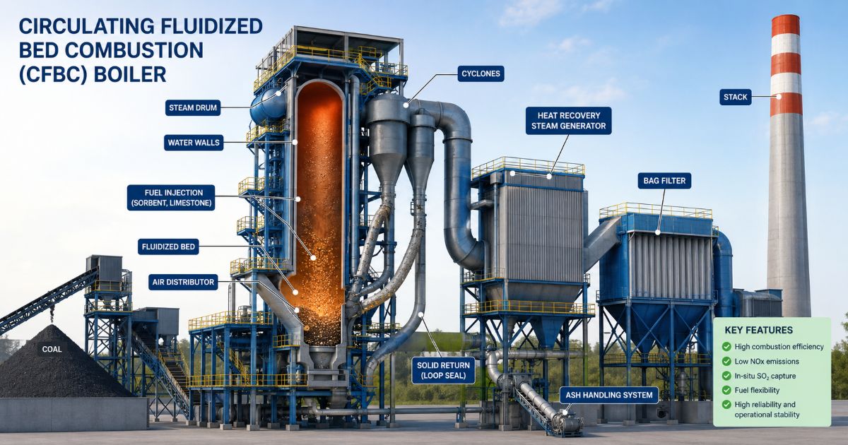
A CFBC boiler uses higher air velocity (4-8 m/s) to carry bed particles, fuel, and ash through the furnace. A cyclone separator captures these solids and returns them via a loop seal, creating a continuous circulation loop. This results in longer residence time, near-complete combustion (up to 99% efficiency), and the ability to burn a wide range of fuels. Combustion temperature is maintained at 850°C to 900°C.
Why CFBC Is Preferred for Large-Scale Plants:
-
Superior combustion efficiency
-
Burns low-grade coal, high-ash fuels, pet coke, biomass, and washery rejects
-
Lower fuel consumption
-
Reduced emissions without extensive secondary pollution controls
-
Better load response and operational flexibility
-
Capacities up to 1000+ TPH
CFBC Boiler Working Principle
The solid circulation mechanism is the heart of CFBC technology. Primary air fluidizes the bed; secondary air completes combustion higher in the furnace.
High gas velocity entrains particles into the cyclone, where solids are separated and returned to the furnace bottom through the loop seal.
This furnace-to-cyclone circulation loop ensures stable temperature, better heat transfer, and complete fuel burnout.
Process Flow Diagram (textual):
-
Fuel Flow: Fuel Bunker → Feeder → Furnace → Combustion Zone
-
Air Flow: FD Fan → Primary Air System → Air Nozzles → Furnace; FD Fan → Secondary Air System → Furnace
-
Solids Circulation: Furnace → Hot Cyclone → Loop Seal → Furnace
-
Water/Steam Flow: Feed Water → Economizer → Drum → Water Wall Tubes → Evaporator → Superheater → Steam Header → Turbine
-
Flue Gas Flow: Furnace → Cyclone → Superheater → Economizer → Air Preheater → ESP → Chimney
Main CFBC Boiler Components
-
Hot Cyclone - Separates solid particles from flue gas, recovers unburnt fuel, and maintains the circulation loop.
-
Loop Seal - Returns solids to the furnace while preventing flue gas backflow; essential for pressure balance.
-
Fluidized Bed Heat Exchanger (FBHE) - Recovers heat from circulating solids to control furnace temperature and optimize steam parameters.
-
Bed Ash Cooler - Cools discharged bottom ash and recovers useful heat, protecting downstream equipment.
-
Air Nozzle - Distributes primary air uniformly to ensure stable fluidization across the entire furnace cross-section.
CFBC Boiler Water Circulation
Water circulation is critical for heat transfer and tube safety. It can be natural (driven by density difference) or assisted (using a pump).
|
Parameter |
Natural Circulation |
Assisted Circulation |
|
Driving Force |
Density Difference |
Circulation Pump |
|
Complexity |
Simple |
More complex |
|
Power Requirement |
None |
Additional power needed |
|
Reliability |
High |
Moderate |
|
Application |
Subcritical Boilers |
High Capacity Boilers |
Proper circulation ensures efficient heat absorption, stable steam generation, and prevents tube overheating.
CFBC Boiler Bed Material and Fuel Requirements
In CFBC, the bed material (sand, ash, limestone, partially burned fuel) continuously circulates. Typical average particle size is 0.1-0.5 mm, with a density of 1200-1800 kg/m³. Correct sizing ensures stable fluidization; oversized particles cause poor circulation and uneven combustion.
Coal and Fuel Size Recommendations:
|
Fuel Type |
Recommended Size |
|
Coal |
0 - 10 mm |
|
High Ash Coal |
0 - 8 mm |
|
Lignite |
0 - 10 mm |
|
Pet Coke |
0 - 6 mm |
|
Biomass |
5 - 25 mm |
Incorrect sizing leads to incomplete burnout, higher carbon loss, and efficiency drops.
Flue Gas Velocity in CFBC Boiler
Velocity controls particle entrainment and circulation. Typical values:
-
Lower Furnace: 4 - 6 m/s
-
Upper Furnace: 5 - 8 m/s
-
Cyclone Inlet: 15 - 25 m/s
Velocity Effect: Too low velocity reduces circulation and burnout; too high velocity increases erosion, cyclone wear, and fly ash losses.
CFBC Boiler Startup, Light-Up and Commissioning
CFBC Startup Procedure:
-
Pre-startup checks: pressure parts, refractory, fuel/air/ash systems, instrumentation, safety interlocks.
-
Bed preparation: charge furnace with sand/ash to required level.
-
Fluidization: supply primary air; monitor bed pressure and draft.
Light-Up Procedure:
-
Purge the furnace, then ignite the startup burner.
-
Raise bed temperature gradually to 450-550°C before starting fuel feed.
-
Increase fuel and air while monitoring steam parameters, oxygen, and bed temperature until reaching full load.
Commissioning Procedure:
-
Mechanical completion: verify hydro test, refractory, electrical, and instrumentation.
-
Cold and hot trials to confirm fan operation, fuel/ash systems, and controls.
-
Performance guarantee test: confirm efficiency, capacity, fuel consumption, and emissions compliance.
Difference Between CFBC and AFBC Boiler
This detailed comparison table highlights the key distinctions to aid selection.
|
Parameter |
AFBC Boiler |
CFBC Boiler |
|
Operating Velocity |
Low (1-3 m/s) |
High (4-8 m/s) |
|
Bed Material Size |
0.8-1.5 mm |
0.2-0.5 mm |
|
Fuel Flexibility |
Good, with some limitations |
Excellent; burns almost all solid fuels |
|
Combustion Efficiency |
90-95% |
97-99% |
|
Emissions |
Low NOx and SOx |
Lower due to better combustion & limestone use |
|
Boiler Capacity |
Up to ~150 TPH |
Up to 1000+ TPH |
|
Capital Cost |
Lower initial investment |
Higher (cyclone, loop seal systems) |
|
Maintenance |
Simpler operation and maintenance |
More complex due to additional components |
|
Combustion Technology |
Bubbling fluidized bed; particles remain in bed |
Circulating bed with continuous recirculation |
|
Particle Circulation |
Minimal |
Continuous furnace-cyclone circulation |
|
Ash Handling |
Simpler system |
Advanced system with bed ash and fly ash management |
|
Load Response |
Moderate |
Excellent load-following capability |
Boiler Efficiency: AFBC vs CFBC
AFBC Boiler Efficiency Range: Typically 80% to 88%, influenced by fuel quality, bed temperature (800-900°C), excess air control, and heat recovery system condition.
Optimizing fuel size, regular cleaning of economizers, and controlling air-fuel ratio can push efficiency to the upper limit.
CFBC Boiler Efficiency Range: Typically 85% to 92% due to longer residence time, superior mixing, and better burnout. The continuous circulation loop ensures minimal unburnt carbon.
|
Parameter |
AFBC Boiler |
CFBC Boiler |
|
Boiler Efficiency |
80 - 88% |
88 - 92% |
|
Fuel Burnout |
Good |
Excellent |
|
Heat Transfer |
Moderate |
High |
|
Fuel Flexibility |
Good |
Very high |
|
Combustion Control |
Good |
Superior |
|
Unburnt Carbon Losses |
Higher |
Lower |
To improve efficiency, maintain proper bed conditions, control excess air, reduce heat losses, and perform regular maintenance.
Common Operating Issues and Troubleshooting
AFBC Boiler Problems
-
Bed Slumping: Caused by insufficient air, blocked nozzles, or high moisture. Correct by ensuring proper primary air flow and cleaning nozzles.
-
Uneven Fluidization: Hot/cold spots due to poor air distribution or oversized bed material. Balance air flow and maintain correct particle size.
-
Agglomeration: Formation of clinkers from high temperature or low ash fusion point fuels. Control bed temperature and fuel blend.
CFBC Boiler Problems
-
Cyclone Erosion: Abrasive circulating particles wear down the cyclone interior.
-
Loop Seal Blockage: Disrupts solids return; monitor pressure balance and periodically inspect.
-
Refractory Damage: Check for hot spots, cracks, and spalling during shutdowns.
-
Ash Handling Issues: Hopper choking and conveyor overload; maintain proper bed ash cooler operation and regular cleaning.
Troubleshooting Approach:
-
Identify symptoms
-
Analyze operating data (temperatures, pressures, DP trends)
-
Inspect equipment
-
Implement corrective actions
Use Root Cause Analysis methods (5 Why, Fishbone, FMEA) to prevent recurrence.
Implement preventive and predictive maintenance - daily monitoring of bed parameters, weekly inspection of nozzles and dampers, and shutdown thickness surveys on erosion-prone areas.
Environmental Benefits
Both AFBC and CFBC boilers reduce environmental footprint:
-
SOx Reduction: Limestone injected into the bed captures sulfur as calcium sulfate.
-
NOx Control: Low combustion temperatures (800-900°C) inherently limit thermal NOx formation.
-
Carbon Footprint: Higher efficiency means less fuel per ton of steam. CFBC boilers can co-fire biomass, further cutting greenhouse gas emissions.
-
Compliance: Combined with ESPs or bag filters, these boilers meet stringent particulate, SO₂, and NOx regulations.
How to Choose Between AFBC and CFBC Boilers
When AFBC Is the Better Choice:
-
Small to medium steam demand (up to ~150 TPH).
-
Limited capital investment.
-
Simpler operation and maintenance teams.
-
Relatively consistent fuel quality.
When CFBC Is the Better Choice:
-
Large-scale power or process plants (1000+ TPH).
-
Need to burn multiple fuels: low-grade coal, pet coke, biomass, washery rejects.
-
Highest efficiency and lowest emissions required.
-
Greater fuel flexibility and superior load response are critical.