
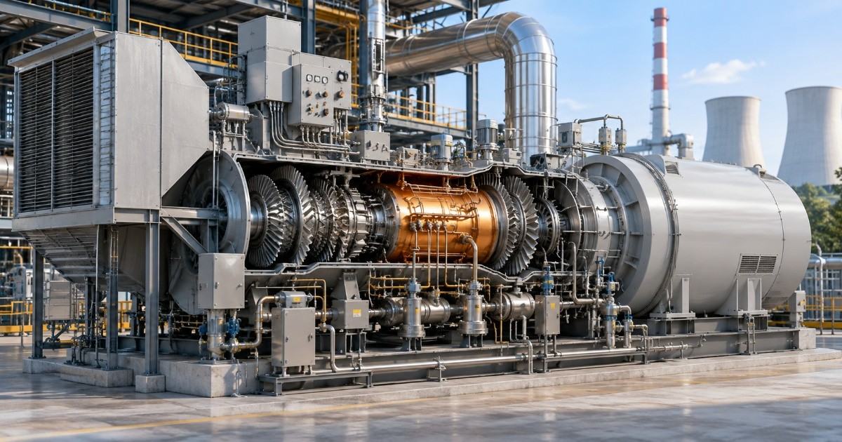
In a thermal power plant, the gas or steam turbine is one of the most important components responsible for converting the thermal energy of gas or steam into mechanical energy, which is then used to generate electricity.
To ensure the turbine operates safely, efficiently, and reliably, several supporting systems known as turbine auxiliaries are required.
Gas Turbine Auxiliary Systems
A gas turbine is a machine that converts the energy of hot combustion gases into mechanical energy. The mechanical energy produced by the turbine is used to drive a generator and produce electricity.
Although the gas turbine is the main rotating machine, it cannot operate safely and continuously without several supporting systems. These supporting systems are called gas turbine auxiliary systems.
Gas turbine auxiliaries are responsible for lubrication, cooling, starting, fuel supply and control, sealing, hydraulic operation, instrumentation and turbine protection.
Proper operation of these systems is essential for reliable turbine operation.
Lubricating Oil System
The lubricating oil system is one of the most important auxiliary systems of a gas turbine. The turbine and compressor shafts rotate at very high speed so their bearings require a continuous supply of clean and properly cooled lubricating oil.
The oil forms a protective film between moving surfaces and reduces friction and wear. It also removes heat generated in the bearings and carries it to the oil cooler.
A typical system consists of an oil tank, main oil pump, auxiliary or emergency oil pump, oil cooler, filters, valves and pressure and temperature instruments.
The main parameters monitored are
1. Lube-oil pressure
2. Lube-oil temperature
3. Oil tank level
4. Filter differential pressure
5. Bearing temperature
If lube-oil pressure becomes too low or bearing temperature becomes too high, an alarm or turbine trip may occur to protect the machine.
Sealing System
Gas turbines operate with high-speed rotating shafts and different areas of the machine require sealing to control the movement of air, gas and oil.
Unlike a steam turbine, a gas turbine normally does not use a conventional gland sealing steam system. Depending on the turbine design, different types of seals can be used, such as labyrinth seals, brush seals and air seals.
The sealing arrangement helps prevent unwanted leakage between different sections of the turbine and compressor. It also helps maintain the required pressure conditions inside the machine.
The exact sealing arrangement varies according to the gas turbine manufacturer and model.
Turning Gear / Barring System
The turning gear or barring system is used to rotate the gas turbine rotor slowly when the turbine is stopped or during the cooldown period.
After shutdown, the turbine components remain at high temperature. If the rotor remains stationary while cooling, different parts can cool at different rates. This may cause thermal distortion or rotor bow.
The turning system slowly rotates the rotor and helps achieve more uniform cooling.
Cooling System
Cooling is very important in a gas turbine because the turbine operates at extremely high temperatures.
Cooling systems are used for auxiliary equipment and, in advanced gas turbines for protecting hot-section components such as turbine blades and vanes.
Cooling may involve
1. Closed cooling water
2. Lubricating-oil cooling
3. Compressor bleed air
4. Dedicated component cooling arrangements
The cooling system maintains equipment temperature within the permitted operating range and prevents overheating.
Fuel Supply and Fuel Control System
The fuel system supplies fuel to the combustion system and controls the quantity of fuel entering the gas turbine.
The amount of fuel supplied must be controlled according to turbine load and operating conditions.
During startup, the fuel system must establish the required fuel flow safely. During normal operation, it continuously adjusts fuel flow according to the required power output.
The system may include fuel pumps, filters, control valves, shut-off valves, fuel pressure instruments and fuel control equipment.
Important parameters include
1. Fuel pressure
2. Fuel flow
3. Fuel temperature, where applicable
4. Control valve position
5. Fuel leakage detection
A problem in the fuel system can result in flame failure, load reduction or turbine trip.
Hydraulic and Control Oil System
Hydraulic or control oil systems provide hydraulic power to operate various actuators and control mechanisms.
Depending on the gas turbine design, hydraulic systems may be used for fuel control valves, inlet guide vanes, variable geometry systems or other turbine control functions.
The system normally consists of hydraulic pumps, oil tanks, filters, accumulators, control valves, actuators and pressure monitoring instruments.
Proper oil pressure and cleanliness are important because contamination or loss of hydraulic pressure can affect valve and actuator operation.
Starting System
A gas turbine cannot normally start by itself from standstill. An external starting system is required to rotate the compressor and turbine shaft until the required starting speed is reached.
Different gas turbines may use different starting methods, such as
1. Electric starting motor
2. Hydraulic starting system
3. Pneumatic starting system
4. Static frequency converter (SFC)
During startup, the starting system accelerates the rotor. Once the turbine reaches the required speed and stable combustion is established, the starting system is disengaged according to the turbine control sequence.
Air Intake and Exhaust System
A gas turbine requires a large quantity of clean air for combustion. The air intake system supplies filtered air to the compressor.
The system generally includes air filters, silencers, ducts, inlet guide arrangements and associated monitoring instruments.
After combustion and expansion through the turbine, hot exhaust gases leave the turbine through the exhaust system.
The exhaust system directs these gases safely away from the turbine. In a combined-cycle power plant, the exhaust gas can be directed to a Heat Recovery Steam Generator (HRSG) for producing steam.
Instrumentation and Control System
Instrumentation and control systems continuously monitor the gas turbine and its auxiliary systems.
Important parameters include
1. Turbine speed
2. Exhaust temperature
3. Exhaust temperature spread
4. Bearing temperature
5. Bearing vibration
6. Lube-oil pressure and temperature
7. Fuel pressure
8. Compressor pressure
9. Air inlet conditions
10. Valve positions
Sensors and transmitters send these measurements to the turbine control system. The control system uses this information to maintain safe and efficient operation.
Safety and Protection System
Gas turbines operate at high speed and high temperature, so protection systems are essential.
The protection system continuously checks important operating conditions. If a dangerous condition is detected, the turbine can automatically trip.
Typical gas turbine protections include
1. Overspeed
2. High vibration
3. High bearing temperature
4. Low lube-oil pressure
5. Flame failure
6. High exhaust temperature
7. High exhaust temperature spread
8. Abnormal fuel pressure
9. Compressor-related abnormal conditions
The main purpose of these protections is to prevent serious damage to the turbine and associated equipment.
Steam Turbine Auxiliary Systems
A steam turbine converts the thermal and pressure energy of steam into mechanical energy. The turbine shaft is connected to a generator, which converts this mechanical energy into electrical energy.
A steam turbine requires several auxiliary systems to control steam admission, lubricate bearings, maintain condenser vacuum, handle condensate, seal the turbine glands and protect the turbine.
These systems are particularly important during startup, normal operation, shutdown, and emergency conditions.
Lubricating Oil System
The lubricating oil system supplies clean and cooled oil to the steam turbine bearings.
Steam turbine rotors operate at high speed and their bearings must maintain a proper oil film to prevent metal-to-metal contact. The oil also removes heat from the bearings.
A typical lube-oil system includes
1. Main oil pump
2. Auxiliary oil pump
3. Emergency oil pump
4. Oil tank
5. Oil cooler
6. Oil filters
7. Pressure and temperature instruments
Important parameters include lube-oil pressure, temperature, tank level, filter differential pressure and bearing temperature.
Low oil pressure can be dangerous because it can cause bearing damage. Therefore, low lube-oil pressure protection is normally provided.
Gland Sealing System
The gland sealing system is an important auxiliary system of a steam turbine.
The turbine shaft passes through the casing and small clearances exist around the shaft. At the high-pressure end, steam can leak outside the turbine. At the low-pressure end, air can enter the turbine because the condenser operates under vacuum.
The gland sealing system supplies sealing steam to control these leakages.
It performs two important functions
1. Prevents steam leakage from the turbine.
2. Prevents atmospheric air from entering the low-pressure turbine and condenser.
The system may include gland sealing steam supply, gland condenser, control valves and associated instruments.
A properly operating gland sealing system helps maintain condenser vacuum and turbine efficiency.
Turning Gear System
The turning gear, also called the barring gear, slowly rotates the steam turbine rotor when the turbine is shut down or during certain startup conditions.
Steam turbine rotors are large and can remain at high temperature after shutdown. If the rotor remains stationary during cooling, uneven cooling can cause rotor bending.
The turning gear rotates the rotor slowly and provides more uniform cooling. It also helps ensure that the rotor is in the correct condition before the next startup.
Condensate Extraction System
After steam expands through the turbine, it enters the condenser. The condenser converts exhaust steam into water, which collects in the condenser hotwell. This water is called condensate. The Condensate Extraction Pump (CEP) transfers the condensate from the hotwell to the feedwater system.
The flow is
Condenser → Hotwell → CEP → LP Heaters → Deaerator
The condensate extraction system maintains the required hotwell level and ensures continuous circulation of condensate through the steam-water cycle.
Vacuum System
The condenser of a steam turbine operates under vacuum. Maintaining a good vacuum allows the exhaust steam to expand to a lower pressure and improves turbine efficiency.
The vacuum system removes air and other non-condensable gases from the condenser.
Common equipment includes
1. Steam jet air ejector
2. Liquid ring vacuum pump
3. Air extraction system
4. Vacuum breaker (safety valve)
Poor condenser vacuum increases exhaust pressure and reduces turbine efficiency. Very low vacuum can also result in a turbine protection trip.
Cooling Water System
The cooling water system, cooling water absorbs the latent heat of vaporization from the exhaust steam. This causes the steam to condense back into water so it can be pumped back to the boiler.
Cooling water can be used for:
1. Lube-oil coolers
2. Hydraulic/control oil coolers
3. Other plant auxiliary equipment
A thermal power plant may have a closed cooling water system and a separate circulating-water system for the main condenser. The condenser requires a large quantity of cooling water to convert exhaust steam back into condensate.
Hydraulic and Control Oil System
The hydraulic/control oil system provides the power required to operate important steam turbine valves.
The system can operate
1. Main steam stop valves
2. Control/governing valves
3. Reheat stop valves
4. Intercept valves
These valves must operate quickly and reliably because they control steam admission to the turbine. The system normally contains hydraulic pumps, oil tanks, filters, accumulators, control valves, actuators and pressure monitoring instruments.
Loss of hydraulic pressure or contamination of the control oil can affect valve operation and may cause a turbine trip.
Steam Admission and Governing System
The steam admission and governing system controls the quantity of steam entering the turbine.
When the generator load increases, the governing system increases steam flow. When the load decreases, steam flow is reduced.
The main components include
1. Main steam stop valves
2. Control/governing valves
3. Reheat stop valves
4. Intercept valves
5. Hydraulic/electro-hydraulic actuators
6. Turbine control system
The governing system helps maintain turbine speed and control generator load.
During an emergency, the protection system can rapidly close the steam valves and stop steam admission to the turbine.
Turbine Drains and Flash Tank System
During startup, shutdown and low-load operation, steam can condense inside steam lines, valves, turbine casings and other equipment.
This condensate must be removed through the turbine drain system. If water accumulates inside the steam path, it can cause water hammer and may damage turbine blades.
The drains can be routed to a flash tank. When high-pressure hot condensate enters the lower-pressure flash tank, a portion of the water changes into steam. This is called flash steam.
The flash tank safely handles high-energy drain water and separates flash steam from the remaining condensate.
Auxiliary Steam System
The auxiliary steam system supplies steam to different plant systems when the main turbine steam supply is not available or is insufficient.
Auxiliary steam can be required for
1. Gland sealing
2. Deaerator heating
3. Steam ejectors
4. Boiler auxiliary services (like soot blower, fuel heating)
5. Startup requirements
This system is especially important during turbine startup because the main turbine has not yet reached normal operating conditions.
Instrumentation and Control System
Instrumentation and control systems continuously monitor the operating condition of the steam turbine.
Important parameters include
1. Turbine speed
2. Bearing temperature
3. Bearing vibration
4. Lube-oil pressure
5. Steam pressure
6. Steam temperature
7. Condenser vacuum
8. Exhaust pressure
9. Condensate level
10. Valve position
11. Axial displacement
RTDs, thermocouples, pressure transmitters, level transmitters, flow transmitters, vibration sensors and speed sensors are commonly used.
The turbine control system receives these signals and automatically controls various turbine functions.
Safety and Protection System
Steam turbines operate at high speed, high temperature, and high pressure. Therefore, a reliable protection system is essential.
The protection system monitors critical parameters and trips the turbine when a dangerous condition occurs.
Common steam turbine protections include
1. Overspeed
2. Low lube-oil pressure
3. High bearing temperature
4. High vibration
5. High axial displacement
6. Excessive differential expansion
7. High rotor eccentricity
8. Low condenser vacuum
9. High exhaust pressure
10. Abnormal steam conditions
The main purpose of the protection system is to prevent major turbine and generator damage.